Underfloor Wheel Lathe
High Precision
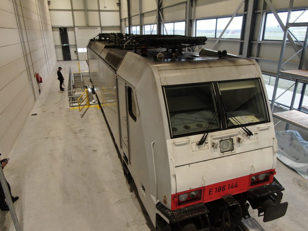
Locomotives travel fast distances all over Europe. Many parts of the locomotive are exposed to long lasting stress cycles which causes fatigue. However, no other part has to endure such high forces as the locomotive wheels. Made from steel, these wheels are under constant stress from all of the locomotive weight. This stress is amplified by rail imperfections, railroad switches and tractive voltages. High temperatures can arise from this and combined with all the stresses, this can cause damage to the wheel. Both on the surface as below the surface.
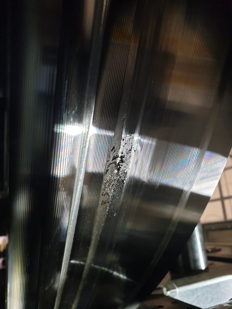
Especially during the initial get away from a standstill, the stresses can be very high. As the train driver applies full power, a high voltage will go trough the wheel and into the railway surface. Normally this would not be very critical as the train moves. But when a train is standing still, the same small piece of wheel surface area is exposed to a high voltage for a relatively long time. This will cause high temperatures resulting in damage to the material. This is called “electrical pitting”.
What starts as a small damaged spot under the surface can quickly turn into a big surface crater. This kind of damage when let unfixed, can cause issues from small vibrations all the way to derailing! This of course needs to be prevented at all times. Therefore, locomotive wheels need regular inspections in order to check their state, and if necessary, undergo maintenance. LWR offers these services from detailed inspection all the way to maintaining the wheels on our very own in house underfloor wheel lathe. This whole process can be done without dismounting the axle!
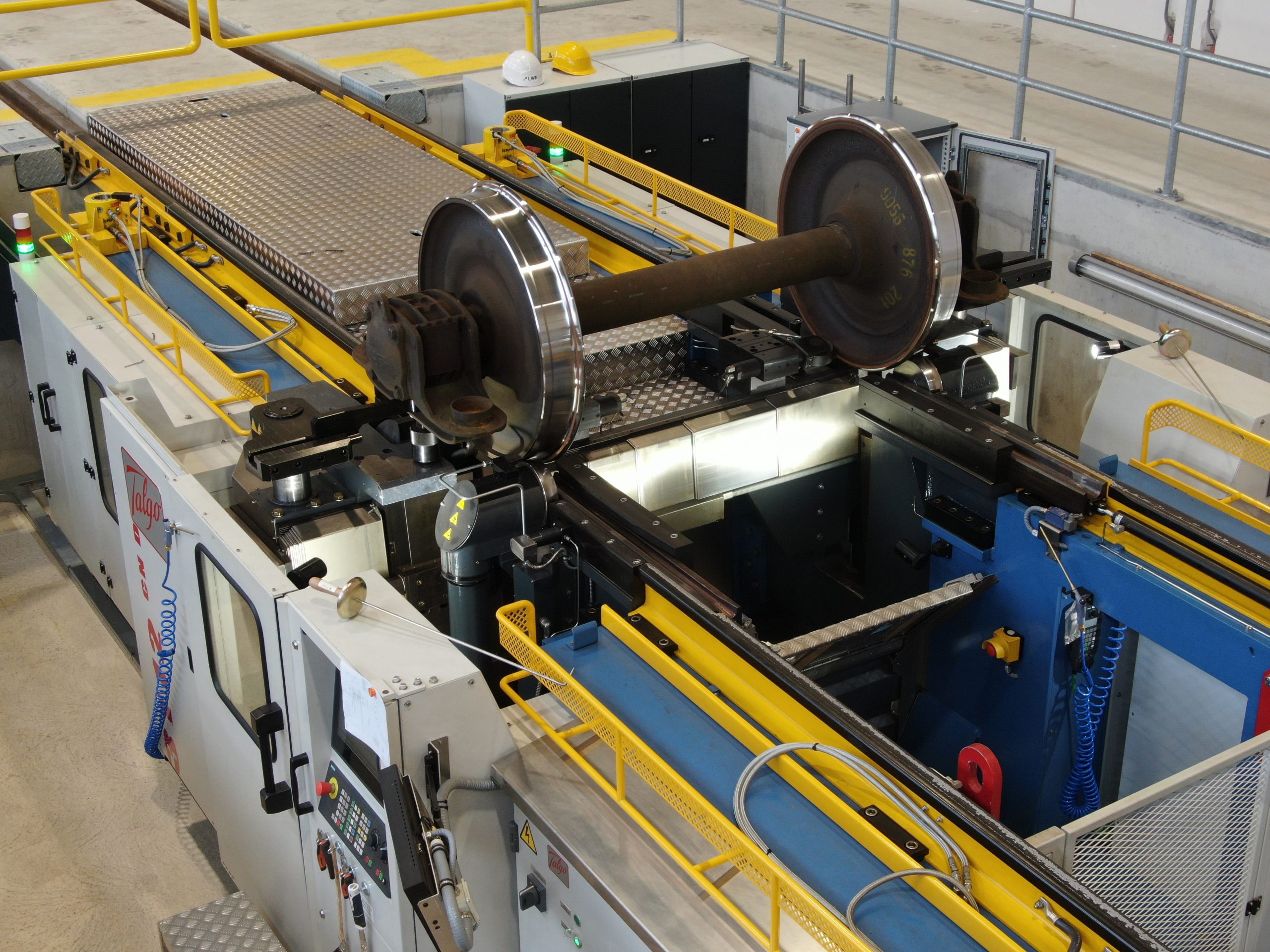
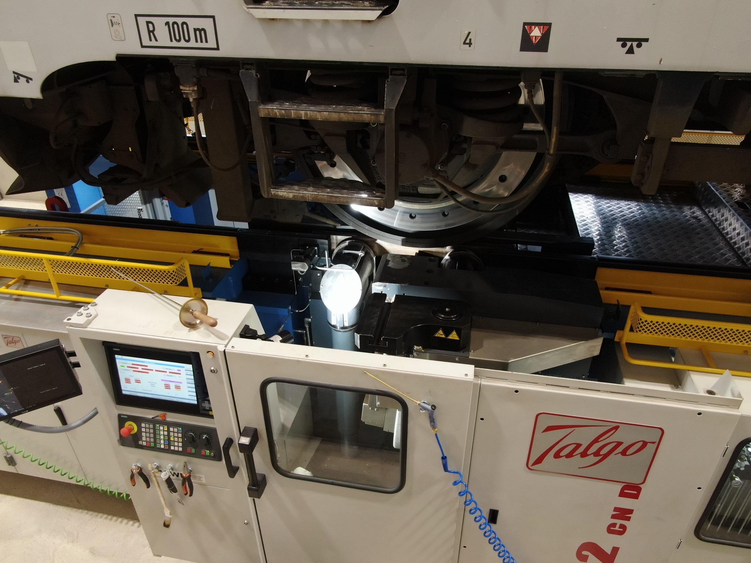
When a locomotive enters our workshop it first undergoes visual inspection. During this step our experienced crew is looking for surface damage and also signs which tell if there is damage under the wheels surface. In order to do any further work on the underfloor wheel lathe, the locomotive wheels, need to be able to rotate freely. This is done by lifting the chassis a bit so that the wheels can “float”. After this, the various wheel dimensions are measured on the lathe (Diameter, wheel flange height, QR etc). This is done with probes and encoders to accurately determine these values. This together with the results of the visual inspection is then combined in a report which is used for consulting with the customer. The customer decides in the end if he wants his wheels to be processed on the lathe or not. If he decides to, the lathe operator will determine how much material will be cut off. In some very extreme cases a whole train wheel axle change could be required.
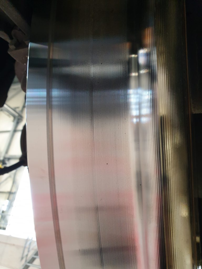
For proper wheel-track interface, all the train wheels need to end up within the same diameter range. The difference in diameter of two wheels on the same axis can only be 2mm. The difference between wheels of two axis on the same boogie can be a maximum of 25mm. Wheels from different boogies may only have a difference of 40mm. Therefore, the wheel which is in the worst state will be started on. From there, the other wheels are processed. Our operator uses the lathe’s cutting plate to trim material of the wheels. With doing this, the diameter, height and width of the wheel can be adjusted as desired. The underfloor wheel lathe can work on two wheels simultaneously, again saving time. The lathes cutting tool is not operated manually, as this will increase the chances of human error. It is instead operated with a preprogramed cutting cycle. This can be set up for the various types of locomotives and for the various dimensions of the wheels (Which the lathe already knows because he just measured them).
The operator always tries to fix the wheels by taking away the least amount of material possible. A train wheel has only a certain thickness of steel which can be used for driving. After this thickness is used up the inner core ring is exposed. This indicates that the train wheel needs to be swapped. Naturally, one tries to postpone this as long as possible as train wheels don’t come cheap!
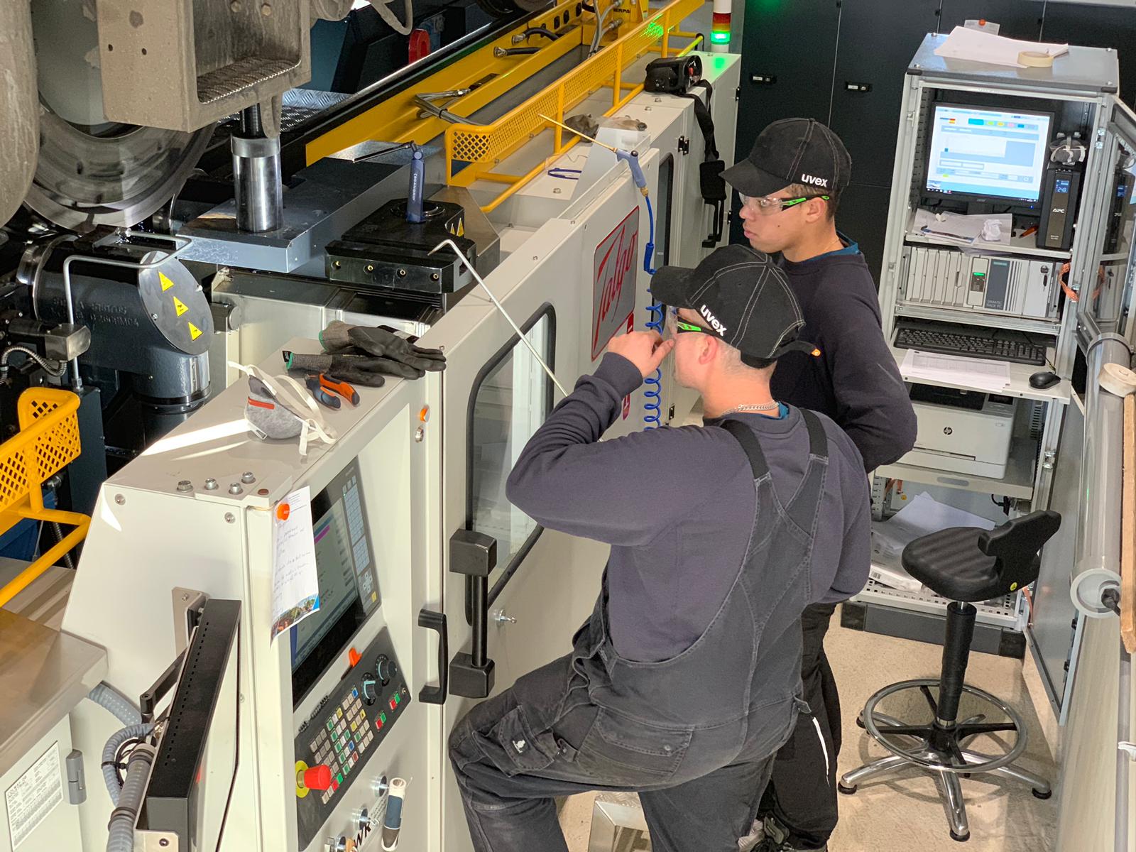
Even though this is an automated process, the operator always keeps a close eye on the wheels. Keeping his attention to the damaged spots in order to see if they reduce in size. If they for instance increase in size while turning, that could indicate that there is much bigger damage under the surface. The operator then needs to adapt the turning process in order to prevent the damage form worsening much further. Once the turning process of an axis is done the final dimensions are measured. These are then used for the final report which will be send to the customer. Next, the operator moves the locomotive so that the next axis is aligned with the lathe. On average the whole process of lathing all axis of a locomotive takes around four hours. However, this can differ from case to case depending on the damage.
Re-calibration of the entire measuring and cutting system is done once every three months. After each machined locomotive, the lathe will undergo inspection and if necessary also maintenance. This ensures that the lathe keeps delivering high quality work.
One of the additional services that LWR offers is the maintenance of brake disks. Often the customer lets us know if a brake disk is defect and needs maintenance. Train drivers can often feel if disks are damaged similarly like with a car, vibrations are felt by the driver. Special cutting tools are available on the lathe to trim of the brake disks. This process is done manually by the operator.
“Cutting of the minimum amount of material while still preserving a high quality final product “
One final thing to notice: all the material that comes of the wheel’s lands on the bottom of the lathe. Here a big crushing mechanism is present which literally crushes the metal bits into smaller pieces. These are then transported via a convey to a storage container. Once this container is full, it is brought to our metal recycling partner. All of this scrap metal is reprocessed in eco-friendly ways to prevent them from harming the environment.
Technical features
Capacities and Performance parameters:
Machining tolerances: